my first driver: ec11 rotary encoder
Last week, I started tackling my first task: interacting with an EC11 rotary encoder. I ordered this one on AliExpress.
I started by finding a video explaining how rotary encoders work. I found this video very helpful. It explains that inside the rotary encoder, there’s a contact wheel. As you turn the knob, it briefly connects the circuit for the A and B pins at slightly different times. See the diagram below.
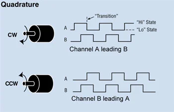
The idea is that because the signals change at different times, you can tell which way the knob is turning based on the last reading. For example, if the last reading was:
A: 0 B: 1Take a second to find that on each of the lines of the diagrams above. Let’s say the next reading is:
A: 1 B: 1Can you tell which way the knob turned? It was counter-clockwise.
If that didn’t make much sense, go watch the video I linked. It was super helpful.
Once I understood that concept, I tried writing a driver for it. The first step was to figure out libgpiod, which was pretty straightforward. I want to write this project in C++, so I read their documentation for the C++ bindings and made a little blinking led circuit. It was my first controller circuit!
Next, I tried decoding the EC11. I wanted to do it on my own, without a step-by-step guide. My first couple attempts seemed correct to me, but the readings were sporadic and unpredictable. If I turned the knob 1 click by 1 click it worked correctly, but as soon as I went fast it would break.
I looked for some help online. After reading about contact bounce, I found this article that shed some light on the best way to decode these encoders. After I understood how it worked, I closed the tab and wrote it myself. I wanted to make sure I really understood.
The issue with my implementation was that I assumed the signals were perfect. Because of the way the contact wheels are built, the contacts touch and stop touching many times during a single turn. That leads to unpredictable signals that have to be cleaned up. You can clean it up by adding debounce components to the circuit, but there’s an elegant way to do it in software as well.
Remember above when we said you can tell which way the encoder is turning based on the previous state? The new system uses that principle. It uses this 2D array as a lookup table:
// given [prev_state][cur_state]
// did it move cw (1) or ccw (-1)
const int _state_mappings [4][4]= {
  {0, -1, 1, 0}, // prev = 0
  {1, 0, 0, -1}, // prev = 1
  {-1, 0, 0, 1}, // prev = 2
  {0, 1, -1, 0}, // prev = 3
};
The state is stored in 2 bits with the formula (a_state << 1) | b_state;, where a_state and b_state are 0 or 1. That means that the range of the state is 0 to 3 when state is read as an integer.
The first dimension uses the previous state of the encoder. The second dimension uses the current state of the encoder. Based on the previous state, we know which state indicates CCW, which state indicates CW, and which states are invalid. For example, using our example from above:
prev_state = 1 (A = 0 B = 1)
cur_state = 3 (A = 1 B = 1)
In our lookup table, we get -1, or counter-clockwise. Perfect!
Notice how if a state is invalid we get 0. This allows us to filter out invalid signals no matter how messy the contact bounce is.
There’s one more step. The encoder I have only clicks once every cycle from 00-00. That means it needs 4 events in a row before the event should trigger. For that, I created a step_count variable. Every time state was updated, I added the output of the state mapping to step_count, and when it exceeded 4 or -4, I reset the counter and triggered an event. This implementation ignores turns unless a click is felt by the user. Here’s what the loop looks like:
for (const auto& event : buffer) {
  int state;
  if (event.type() == gpiod::edge_event::event_type::RISING_EDGE) {
    if (event.line_offset() == _a_line) {
      state = prev_state | 0b10;
    }
    if (event.line_offset() == _b_line) {
      state = prev_state | 0b01;
    }
  }
  if (event.type() == gpiod::edge_event::event_type::FALLING_EDGE) {
    if (event.line_offset() == _a_line) {
      state = prev_state & 0b01;
    }
    if (event.line_offset() == _b_line) {
      state = prev_state & 0b10;
    }
  }

  // here’s the step_count I was talking about
  step_count += _state_mappings[prev_state][state];
  if (step_count >= 4) {
    _cw_cb();
    step_count = 0;
  }
  if (step_count <= -4) {
    _ccw_cb();
    step_count = 0;
  }
  prev_state = state;
}
The last thing I did was take my logic and put it in a class. The constructor takes an offset for each pin, and a callback function for each event. It spawns a thread to watch the encoder, and it can also spawn a thread to watch the button pin (you can see how I processed button clicks in the source code. It was easy compared to the encoder). I’ll use this class to process volume and input selections for my receiver!
Here’s a video showcasing the final product!