schematics
The next step is to lay out the circuit board(s) for this project. And all good circuit boards start with a schematic.
I wouldn’t have known that before this summer. I didn’t know much of anything about hardware until this summer. A big reason I wanted to take on this project was to teach myself the basics of electrical design. I spent the last 6 weeks working through most of the curriculum on vocademy.net by Bob DuHamel, and I feel like I have the basics now. Enough to be able to make sense of a data sheet.
This weekend I realized I had the skills to start laying out my design. I downloaded EasyEDA and spent 12 hours laying out my design on Sunday. 12 hours. I tend to get obsessive about projects when I feel like I’m making headway.
I spent that time referencing data sheets, comparing ICs, conceptualizing my power distribution, and really solidifying the design that has been floating around in my head for a couple months now. Even though I’ve looked over these designs a dozen times, I’m certain I’ve made some mistake, and I know the design will continue to evolve, but I’m proud to present the first version of schematics for the Rasceiver.
1. the motherboard
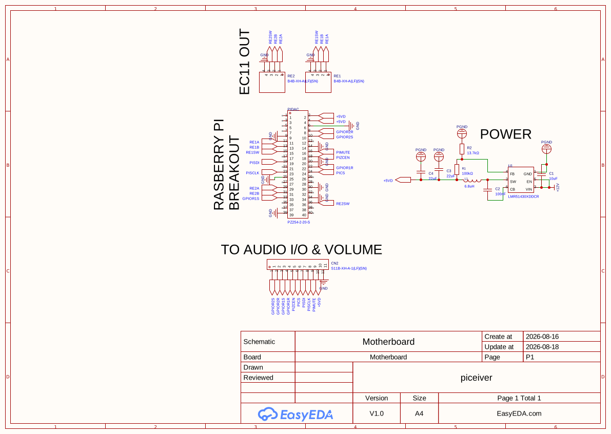
This board is the hub of the design. It connects the Raspberry Pi 4B to the other PCBs via JST connectors.
Highlights:
-
Power Distribution
The power coming in is from a 12V 5A adapter I have from Amazon. I’m using a TI LMR51430 buck converter to step down the power to 5V. This power is used for the digital components. The LMR51430 is rated for 3A continuous, which should work for my design- the main amp draw is the Pi, which shouldn’t need more than that based on my research. The other draws are negligible compared to the Pi. -
The Breakouts
The only other feature of this board are the breakouts. There’s a 40-pin connector that will go to the Pi, two 4-pin connectors that will go to the EC11 boards, and an 11-pin connector to go to the Audio I/O & Volume board. I made the 4 and 11-pin connectors JST because they allow for solder free but reliable connection. The Pi breakout matches the header pins on the Pi.
2. audio i/o & volume
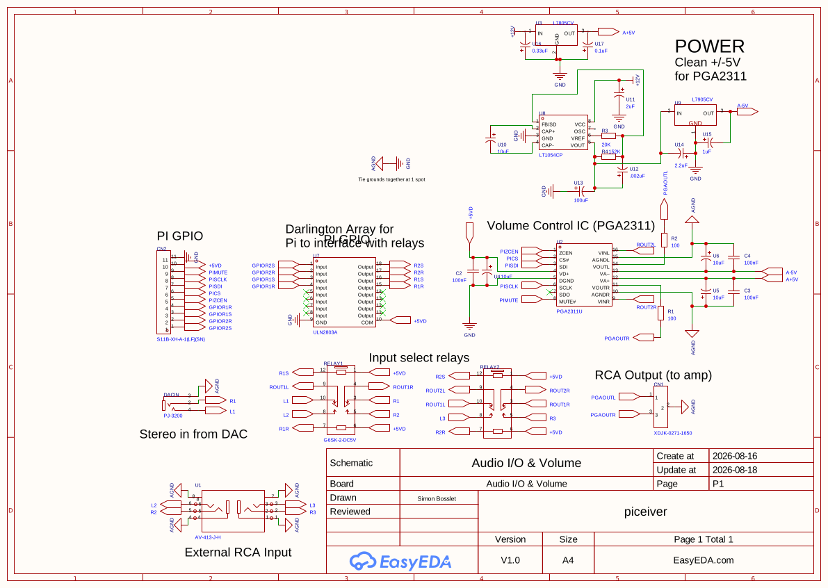
This is the board that does the heavy lifting. It controls the input selection relays, and handles volume control.
Highlights:
-
I/O
There’s three I/O components on this board. The first is a double RCA hub that will allow external input to the receiver. The second is a 3.5mm stereo jack that will run from the DAC to the board to allow for streaming on the Pi. The last is the output RCA jack. -
Volume Control (PGA2311)
I chose the PGA2311 over the MUSES72323 because it doesn’t require external op-amps. I do like that the MUSES72323 is more configurable in that way, and I may revisit this choice in future iterations.
The PGA2311 is controlled from the Pi with 3-wire SPI. It also has a mute pin and a zero-crossing enable pin (more on this once I’m programming the chip) that are controlled with the Pi. Those signals come over the JST connector from the motherboard. -
Power
The PGA2311 requires +/-5V of noise free power to operate correctly. I had to design a circuit to step down the 12V input to +/-5V. I use linear regulators to ensure that the voltage is free of noise. -
Relays
The most interesting part of this board in my opinion is the daisy-chained relay configuration. I chose to use mechanical relays because solid-state relays can distort audio quality. The relays are double-pole double-throw, allowing 1 relay to select both the right and left audio channels. They’re daisy-chained together because each relay can only select from 2 inputs at a time. The output of the first relay (RELAY1) is sent to the input of the second relay (RELAY2), allowing the array to choose from any of the 3 inputs connected to the relays.
The relays are controlled by the Pi. 4 GPIO pins allow the Pi to switch both relays on command. I’ll talk more about this when I write the software for this configuration.
3. ec11 breakout
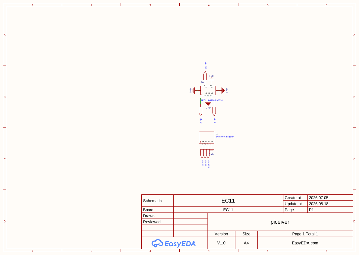
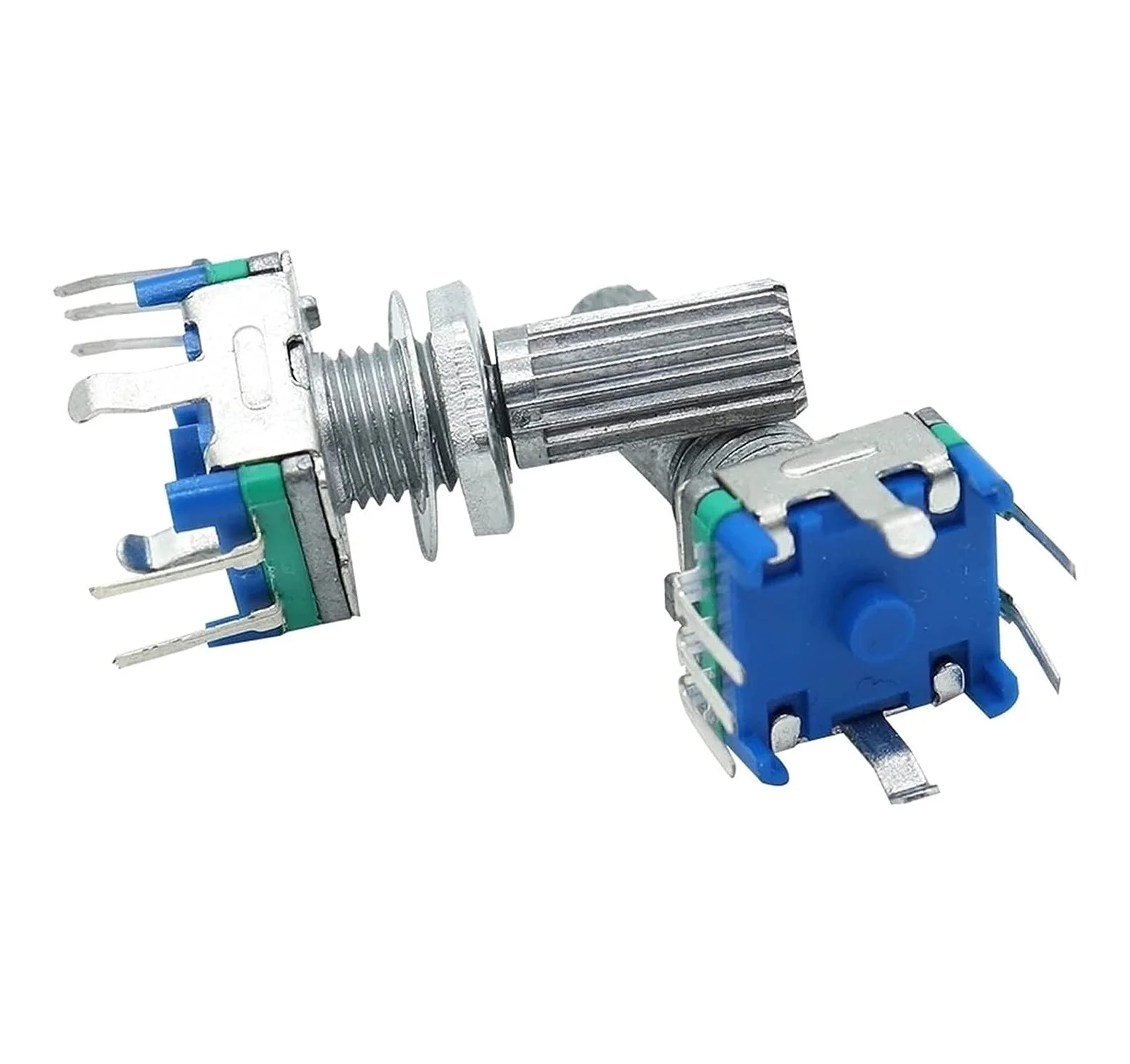
The last board is just a breakout for the EC11 rotary encoder. I don’t even need to worry about mounting holes, since they make EC11s with screw-on mounting.
So, that’s the first iteration. I’m sure it will get edited as I continue to design. The next step is laying out PCBs, which is scary to me… It’ll probably take a while. My next update should be when I have a PCB in hand!